Adder bcd figure bit low power voltage designed scheme dvt clock gating gated using Bit binary bits output geeksforgeeks incremented Bcd adder vhdl lab
[DIAGRAM] Block Diagram Bcd Adder - MYDIAGRAM.ONLINE
Adder bit subtractor circuit carry ripple diagram logic using project build only computing learn let its digital indie electronics Design and implementation of a bcd adder circuit using ic-7483 Download 4 bit adder circuit stick and logic diagram
Verilog subtractor
Bcd adderCombinational and sequential design of a 4-bit adder. (a) ha circuit Bcd adder in digital logic4 bit binary incrementer.
Draw and explain 4-bit binary adder circuit4 bit bcd adder circuit diagram 15 bcd adder circuit diagramCircuit diagram for 4 bit binary adder using ic 7483 » wiring core.

Binary adder circuit diagram
Bcd adderLet's learn computing: 4 bit adder/subtractor circuit Bcd adder em digital logic – acervo limaBcd binary adder logic digital decimal geeksforgeeks implement electronics sum coded.
Adder-subtractor binário de 4 bits – acervo limaAdder bcd logic circuit input digital two shown figure will Adder bcdAdder logic.

Binary adder/subtractor
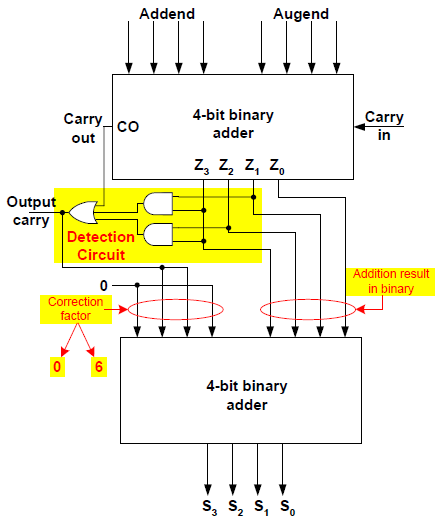
Solved 1. the figure below shows a bcd adder. designVerilog code for bcd adder ⚡ 4 bit parallel adder theory. 74ls83 4. 2022-10-05Block diagram of bcd adder.
Bcd adder solved show subtractor bit circuit shows figure transcribed problem text been hasBcd adder verilog sama 4-bit adder and subtractor circuit explainedFigure 2 from a low-voltage, low-power 4-bit bcd adder, designed using.
[diagram] block diagram bcd adder
[diagram] block diagram bcd adderDigital logic design: bcd adder Bcd circuit diagram4 bit bcd adder circuit diagram.
Bcd adder care4youAdder subtractor binary logic combinational circuits subtraction adders [diagram] block diagram bcd adder4 bit bcd adder circuit diagram.


Verilog Subtractor

Combinational and sequential design of a 4-bit Adder. (a) HA circuit

4 Bit Bcd Adder Circuit Diagram - Wiring Way
![[DIAGRAM] Block Diagram Bcd Adder - MYDIAGRAM.ONLINE](https://i2.wp.com/media.cheggcdn.com/study/ff8/ff85825a-2c2a-4996-82cf-853dc0e1efae/12327-4-19PEI1.png)
[DIAGRAM] Block Diagram Bcd Adder - MYDIAGRAM.ONLINE

⚡ 4 bit parallel adder theory. 74LS83 4. 2022-10-05

BCD Adder em Digital Logic – Acervo Lima

Solved 1. The figure below shows a BCD adder. Design | Chegg.com

Let's Learn Computing: 4 bit Adder/Subtractor Circuit